Failure investigation of heat exchanger plates due to pitting corrosion

1. Introduction
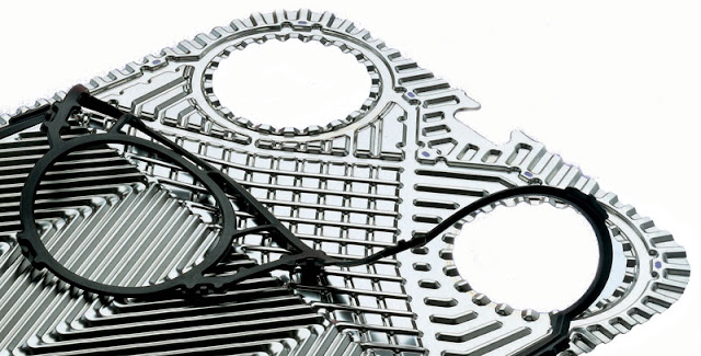
Plate heat exchangers (PHE), often called plate-and-frame heat exchangers, are widely used in dairy and food processing plants, chemical industries, power plants and central cooling systems. They exhibit excellent heat transfer characteristics, which allows a very compact design, and can be easily dismounted for maintenance, cleaning or for modifying the heat transfer area by adding or removing plates. Each plate contains a bordering gasket, which seals the channels formed when the plate pack is compressed and mounted on a frame. The hot and cold fluids flow in alternate channels and the heat transfer takes place between adjacent channels. The corrugation of the plates promotes turbulence inside the channels increase heat transfer efficiency and improves the mechanical strength of the plate pack [1,2]. 316L stainless steel (SS) is a candidate material for the manufacturing of PHE’s plates due to having its good corrosion resistant properties in cooling water but the parameters of normal cooling water determine the overall corrosion stability of a plate heat exchanger such as temperature, pH, conductivity, hardness, alkalinity as well as sulphate, nitrate and most importantly chloride ions concentration [3]. 316L stainless steel is protected by a thin film of chromium oxy-hydroxide and is resistant to corrosion in many aggressive environments. Breakdown of this protective film leads to localized corrosion failures such as pitting/crevice corrosion. The ability of the 316L SS to repassivate after film breakdown determines its resistance against localized failures [4,5].
2. Brief history
AISI 316L stainless steel heat exchanger plates of a textile mill power generation system were submitted for the determination of root cause of failure due to perforation. The provided plates were the part of plate heat exchangers which exchange heat of close circuit jacket water and auxiliary water (primary cooling system) by open circuit cooling tower water (secondary cooling system). These heat exchangers were designed to reduce the engine jacket water and auxiliary water temperature by 20 C. It was disclosed that more than 32 plates have perforated by the cooling tower water (CT water) open circuit side. It was learnt that 316L stainless steel plates in jacket water heat exchangers were arranged in a sequence that a set of two plates were used for jacket water and next set of two plates were used for cooling tower water thus 24 plates were tightened in a bundle. Similar arrangement was maintained in auxiliary water heat exchangers. The systematic detail of cooling system is shown in Fig. 1. It was not possible to ascertain as to which engine these plates belonged. Auxiliary water heat exchangers and jacket water heat exchanger were cooling internal lube oil temperature and cylinder head jackets of power engines in a close circuit systems respectively. In primary cooling system the engine jacket water entry temperature was 60 C and outlet temperature was 80 C from the jacket and on the other hand the auxiliary water entry temperature was maintained at 40 C and outlet temperature was 58 C. In order to provide cooling water at appropriate temperature all the four power engines were connected to four cooling towers in series. The CT water was used to bring down temperature of jacket water and auxiliary water in the heat exchangers. The cooling tower feed water was a blend of raw water and reverse osmosis (R/O) water with a ratio of 1:4 as reported by the client. Each cooling tower has 50 ton/h water capacity. 3. Analytical approach In order to find the cause of perforation of 316L SS plates of PHE the sequence of investigation procedure was as follows:
1. Data collection.
2. Visual observation.
3. Metallurgical investigation.
4. Chemical analysis of raw water, reverse osmosis (R/O) water, CT feed and CT bleed water.
5. Electrochemical study.
3.1. Data collection The client was asked to provide more data relevant to operational parameters, cooling water quality and control chemicals for the system. The client informed the research team that proprietary chemicals were added to the CT water to avoid excessive scaling, corrosion and algae buildup in the system. Sulfuric acid (H2SO4) was used to regulate the pH of the CT water. The dosage levels were as specified by the Local Supplier ‘A’ (LS-A) and are listed in Table 1. Water quality was monitored on a monthly basis and operational parameters were adjusted by LS-A accordingly. A typical chemical analysis of CT water is summarized in Table 2.


3.2. Visual observations
After about 2000 h of operation a power engine was stopped for maintenance, the PHE’s were also opened for cleaning. It was observed that there were no deposits or fouling etc. on the closed circuit side of PHE’s plates but the CT water side (open circuit system) showed severe pitting and sludge (fouling) as shown in Fig. 2. It was also purposed to the client to examine CT pipe lines and bends who reported severe pitting, blistering and fouling as depicted in Fig. 3.
3.3. Metallurgical investigation The samples of PHE plates were chemically analyzed by wet chemical method. The spark emission spectrometric method could not be used for analysis as the thickness of the plates was very thin. Specimens for microstructural study were also cut from both the sound and pitted areas. The samples were cold mounted and ground by following standard Metallography practice [6]. The samples were then polished and etched electrolytically in 10% oxalic acid according to ASTM E-407-99.
3.4. Analysis of water samples Four samples of raw water, reverse osmosis (R/O) water, CT feed and bleed water were analyzed. Special attention was paid to chloride contents. Silver nitrate titration method was adopted for the chloride ions determination in the laboratory


3.5. Electrochemical testing
The samples were taken from sound region of plate for electrochemical testing. Potentiodynamic cyclic polarization and potentiostatic scans methods were selected to investigate the behavior of plate samples in CT feed and bleed water. To check the severity of primary cooling system, auxiliary and jacket water samples were also tested under same electrochemical conditions by these techniques. The electrochemical testing was carried out by using Gamry Potentiostat PC/750 connected to a three electrode cell system. The graphite rod was used as counter electrode, calomel electrode as reference and plate samples served as working electrode. 4.
Results and discussion
4.1. Metallurgical study The chemical analysis results of PHEs plates samples are described in Table 4 and it confirmed AISI 316L as a material of construction for plates. As polished specimens for microstructural study revealed absence of any considerable non-metallic
inclusions, i.e. oxides, sulphides, silicates, or slag particles within the material. It was therefore confirmed that material of 316L plates was metallurgically clean. Another specimen was prepared representing a pitted location as shown in Fig. 4A. It was observed that pit has perforated the total thickness of the plate. The pit was irregular in shape and its dimensions varied between 0.8 and 0.95 mm. The area around the pit was also free from any noticeable non-metallic inclusion. Other prepared and electrolytically etched sample from the upper corrugated surface under microscope revealed cold formed slip bands and annealing twins in the austenite grain matrix. This was a typical microstructure associated with roll formed stainless steel as shown in Fig. 4B. On the whole the microstructure did not show any metallurgical heterogeneity associated with the material except at a few locations where pitting corrosion has started its adverse effect on the austenite grain boundaries by initiating intergranular attack for further pit propagation.
4.2. Analysis of water samples The results of raw, R/O, CT feed, and CT bleed water chemical analysis are presented in Table 5. Special attention was paid to chloride contents of water samples. It was found that chloride level in CT feed and bleed water was 142 ppm and 709 ppm respectively. The high chloride contents in CT feed water were contrary to the recommendations made by LS-B and guide lines provided by manufacturers of the power engine as given in Table 3. The CT bleed water was regulated on the basis of TDS value rather than chloride level. It was obvious that the cooling tower water is not chlorine/chloride free as sodium hypo-chlorite was being continuously added to the CT water. According to LS-A water analysis (Table 2), there was no mention of chloride ions in the report and water quality was being overlooked. Since it is well known that under the action of aggressive ions, i.e. chlorides anions, local breakdown of passivity occurs, and causing pitting corrosion [7]. The laboratory analysis results also reported very high (total dissolved solids) TDS value both in raw water (2020 ppm) and CT bleed water (3060 ppm). This was a clue to determine the cause of fouling of CT pipe lines and PHE’s plates on the open circuit secondary cooling side.


5. Conclusion
The material of the failed plates was confirmed as 316L stainless steel and the material was inclusions free. The chloride/ chlorine contents in the cooling tower system have caused pitting corrosion (perforation) of PHE’s plates on the open circuit side (CT water side). The 316L plate samples also registered very low pitting corrosion resistance in CT feed and CT bleed water during electrochemical testing. The electrochemical results proved the chloride level as a damaging entity. There was complete non-compliance of sound scientific knowledge and practice of the cooling water treatment especially chloride concentration, which cannot be ignored even at ppm level.

6. Remedial measures
1. Water of reverse osmosis (R/O) quality should be used in the CT feed.
2. The qualification of feed water system must focus on chloride contents rather than TDS values.

References
[1] Georgiadis MC, Macchietto S. J Chem Eng Sci 2000;55:1605.
[2] Pearce N. Plate exchanger defeats industry conservatism. Eur Power News 2001(10):16–7.
[3] Petersen B. Guideline of water quality for copper brazed plate heat exchangers. Danfoss district heating. VJ.KV.D2.02 Danfoss 08/2009.
[4] Schmitt G, Bedbur K. In: Proceedings of the ninth international congress on metallic corrosion, Toronto, Canada; 1984. p. 122.
5] Leckie HP, Uhlig HH. J Electrochem Soc 1966;113(1):262.
[6] Vander Voort GF. Metallography: principles and practice. Materials Park (OH): ASM International; 1999.
[7] Pardo A, Merino MC, Coy AE, Viejo F, Arrabal R, Matykina E. J Corros Sci 2008;50:1796.
[8] Thompson NG, Payer JH. DC electrochemical test methods, vol. 6. Houston (TX): NACE International; 1998.
[9] Fontana MG, Greene ND. Corrosion engineering. New York: Mc Graw-Hill Book Co.; 1967. p. 51.
[10] Shreir LL. Corrosion metal/environment reactions. In: Shreir LL, editor, vol. 1. New York: McGraw-Hill Book Co.; 1976. p. 182.
[11] Szklarska-Smialowska S. Localized corrosion. Houston (TX): NACE; 1974. p. 312.
https://www.researchgate.net/profile/Kashif_Mairaj_Deen/publication/245161509_Failure_investigation_of_heat_exchanger_plates_due_to_pitting_corrosion/links/5b5a2ed90f7e9bc79a668b23/Failure-investigation-of-heat-exchanger-plates-due-to-pitting-corrosion.pdf

nice information about the product and a good understanding for new users, and I hope that there will be more articles in the future; if you would like more information, you can visit the Abrasion Resistant Steel Plates
RispondiEliminaThis is really helpful information about the product, and if you would like more information, you can visit the TP904L Stainless Steel
RispondiEliminaThis blog is really helpful to deliver updated affairs over internet which is really appraisable.
RispondiEliminaMS Pipe Weight Chart