Heat Exchanger Standards for Shell & Tube Equipment

Reliable operation of shell-and-tube heat exchangers begins with an appropriate standard. This article provides an overview of those that are applicable
Shell-and-tube heat exchangers are the backbone of the power generation, chemical process, petrochemical and pulp-and-paper industries. They are designed for a wide variety of services, from small-engine oil coolers to large nuclear steam generators. Heat exchangers come in many types and styles, but almost all are designed as unfired pressure vessels. Over the years, several industrial standards have been developed to help end users and manufacturers ensure that their heat exchange equipment will be designed with safety and consistency in mind. The principal reason why shell-and-tube heat exchangers have been so successful for so long is their ability to meet critical design performance objectives with such a wide variety of equipment configurations.
While advancements in micro-channel plate-type heat exchangers have made that class of equipment acceptable, the extensive industrial experience base with shell-and-tube-style heat exchangers, along with the their ability to meet stringent temperature, pressure and mechanical design standards, has made this type of equipment critical to the availability and reliability of many different unit operations (Figure 1).
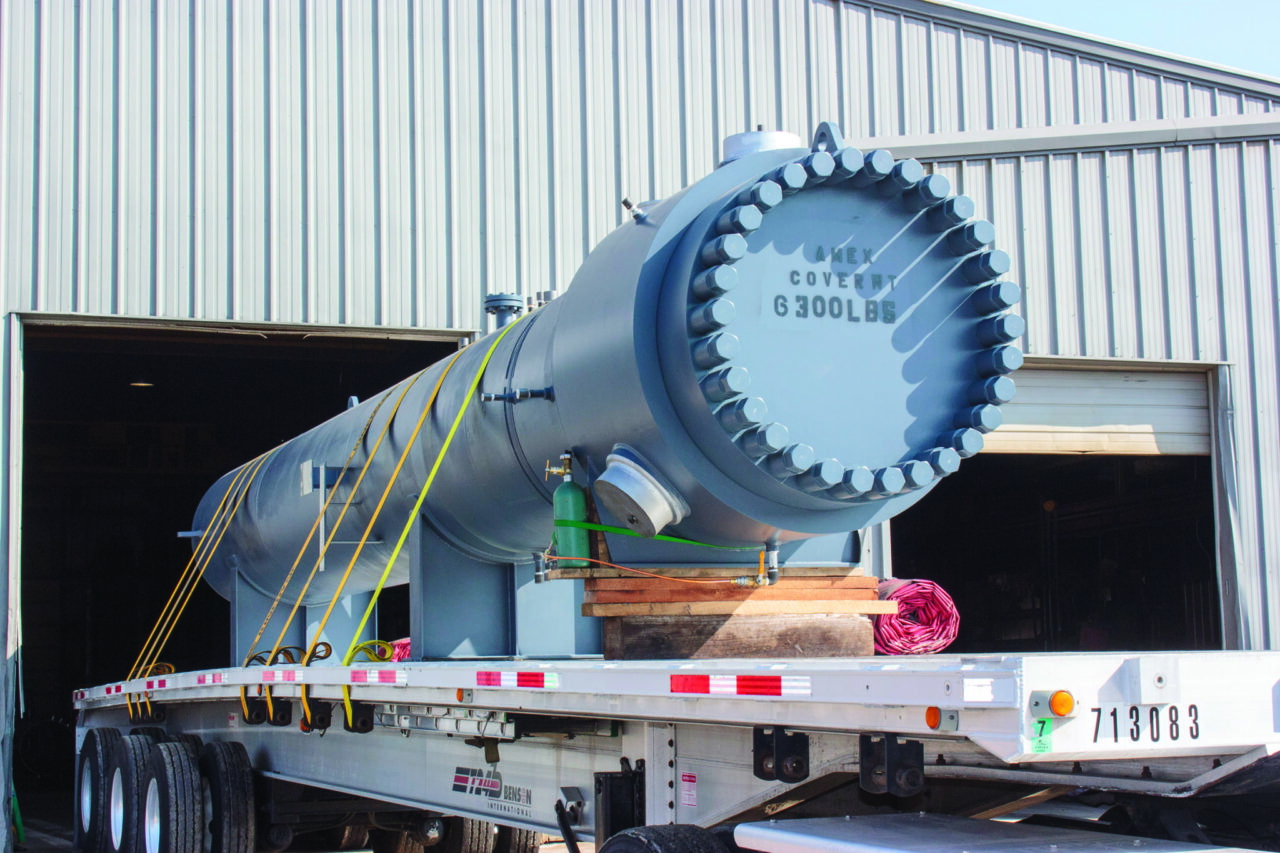
Figure 1. Extensive industrial experience with shell-and-tube heat exchangers has helped make them critical in many types of operations
Achieving mechanical reliability and availability in shell-and-tube heat exchangers, as well as providing units that can be repaired, maintained and cleaned as service factors dictate — whether new or a replacement — starts with choosing a minimum starting point. In most cases, this means choosing an appropriate standard. Because the design possibilities for shell-and-tube heat exchagers are so broad, it is difficult to develop a single, unified industrial standard. This article provides an overview of four standards (or more accurately, three standards and one code) that apply to industrial shell-and-tube heat exchangers.
SHELL-AND-TUBE EXCHANGER OPERATION
Heat exchanger tubes come in a variety of sizes, types and materials. Tubes are the conduit for one fluid that keeps the fluid inside the tube (tube-side fluid) separate from fluid outside the tube (shell-side fluid). Almost always, tubes are circular in cross-section and almost always connect to a tubesheet (or two), which secures the ends of the tubes. The tube inner diameter is usually free-flowing and clear.
Tubes are almost always bundled together and surrounded by a shell. The shell keeps the shell-side fluid in contact with the tubes, which convey the tube-side fluid.
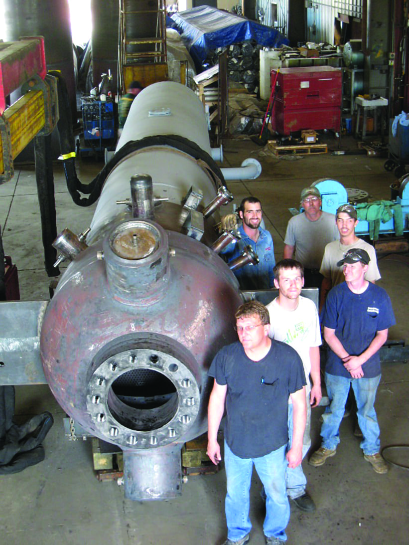
Figure 2. The term “shell-and-tube heat exchanger” incorporates a wide range of equipment variations, such as this model in the shop
This introduction is intended to convey the vast range of equipment encompassed by the term “shell-and-tube heat exchanger” (Figure 2). There are exceptions and variables for most of the general discussion surrounding this type of equipment. Variables to consider include designs, operations and fluids. Tubes can have internal or external fins, which can have varying heights, depending on the heat-transfer characteristics of the fluids involved. It is also possible to have two separate tube-side or shell-side fluid streams. The shell may be much larger than the tube bundle to allow for boiling. The wide range of equipment design variables complicates standards development.
A feature common to all heat exchangers is the flow of heat from one fluid stream to another. There is always a balance between the streams, called the duty. Whenever a difference in temperature exists, heat will flow from the warmer to the cooler object via one or more heat-transfer modes (radiative, conductive and convective). In some situations, such as fired boilers, the energy of the flames is radiated to the tubing, conducted through the tube wall and convected into the tube-side fluid. In unfired heat exchangers, heat is conducted and convected.
Since heat exchangers act through convection and conduction, velocity of the fluids has a significant influence on how fast the heat is transferred. The higher the velocity, the higher the heat-transfer rate, but the more energy it takes to get this higher velocity. The smaller the flow area, the higher the velocity.
STANDARDS AND CODE
Three major industrial standards and one code are discussed here. They are the following: TEMA (Tubular Exchanger Manufacturer’s Association; Tarrytown, N.Y.; www.tema.org) Heat Exchanger Standards; API 660, a shell-and-tube specification developed by the American Petroleum Institute (API; Washington, D.C.; www.api.org); The HEI (Heat Exchange Institute; Cleveland, Ohio; www.heatexchange.org) Standards for Shell-and-Tube Heat Exchangers; and the ASME (American Society of Mechanical Engineers; New York, N.Y.; www.asme.org) Boiler and Pressure Vessel Code (BPVC). It is incumbent upon the end user of the heat exchanger to specify the appropriate pressure-vessel code that the manufacturer must meet.
TEMA STANDARDS
The TEMA Heat Exchanger Standards (referred to here as TEMA) are the broadest available. Currently in its ninth edition, TEMA is a set of global standards first developed in 1939. Largely mechanical standard, TEMA covers most industries, equipment sizes and services. Its overall scope is to provide for a way to communicate between end-users and manufacturers and designers.
There are three equipment classes within TEMA: R, C and B. TEMA describes the classes as follows:
- R: severe petroleum and related processing applications
- C: commercial and general process applications
- B: chemical process service
TEMA standards are written and published by manufacturers. The information in TEMA is provided to help ensure a common understanding of terms, compatible interfaces and to foster realistic expectations between the end-user and the manufacturer. The focus is on manufacturing and mechanical design. Since the standards are built around three different heat exchanger classes, they allow for some fine-tuning of the standard to meet the needs of the end user. TEMA also provides references for thermal design and fouling.There are cost differences between the three heat exchanger classes. TEMA R units are usually more costly, due in part to their greater corrosion allowance. TEMA R units require 1/8-in. thicknesses for carbon steel and low-alloy steel, while B and C units require 1/16 in. TEMA R units also require a more expensive confined joint flange design. The tube spacing may also be larger on TEMA R than B or C. TEMA R also requires confined gaskets and heavier tie rods. Additionally, there are a few other details that incrementally increase the cost of R over B and C.
While the minimum vessel-wall thicknesses may be thicker in TEMA than for the ASME BPVC or other pressure vessel requirements on low-pressure and low-temperature operations, the thicknesses allow for handling and fabrication. The additional cost of the metal is small and helps equalize fabricators.
The TEMA Standards, provides a three-letter design description for heat exchanger configurations. This is an important function of the standard: it is a quick reference to the mechanical design of the heat exchanger. It combines a front head, shell type and rear head. Choosing a configuration is a function of the services the unit will perform and of end-user preference. It may not be straightforward and will require discussions between end-user and manufacturer.
Tubesheets and tubejoints.All the standards discuss tubesheets, critical components for shell-and-tube heat exchangers that separate the shell side from the tube side. Tubesheets are the components to which the tubes are connected. The tube-to-tubesheet connection (also known as tubejoints) can be welded, roller expanded, explosively welded (or bonded), explosively expanded, hydraulic or a combination. The choice of joint configuration can significantly impact price and reliability. There are also several tubejoint welding options, including strength welds, seal welds and bore welds. TEMA and other reference standards have additional details on the types of joints.
Front stationary tubesheet end. One end of the tube bundle needs to have a stationary tubesheet. The tubesheet provides separation between the shellside and tubeside fluids. The tubesheet on the stationary end is fixed and does not move with thermal differential expansion. It is often gasketed between flanges. At least one nozzle is located in the attaching channel. The ability to open and close the channel with more or less ease is part of the choice of channel design.
TEMA rear-head type.In services with high temperatures and long tubes, differential thermal expansion between the tubes and shell may require a method to provide for their differential growth. This can directly impact the type of rear-head configuration. If the fluid is clean and the tube bundle does not need to be removed to be cleaned, the differential expansion may be accommodated with an expansion joint. Within that decision is the choice of which type of expansion joint should be used. Such expansion joints can be of the bellows type or dished heads. Both options are addressed in TEMA.
If the service of the exchanger requires occasional cleaning of the shell side, a removable design would be chosen. The design pressure, fluid service and gasket requirements may dictate one design compared to another. For instance, a “W” head is not used with a four-tube-pass design due to the need for a pass partition in the return head in which the tubesheet needs to move to account for differential thermal expansion. “W” heads are also not suitable for higher design pressures.
U-tube exchangers may not be appropriate for services in which the tubes need to be cleaned. Fouling and debris can accumulate in the U-bends, resulting in tubes being plugged and prematurely failing. In clean tube-side flow service, the U-tubes can be the most cost-effective approach, since it only requires one tubesheet and only an inlet-outlet channel. This is especially important in high-pressure applications. This return end also requires an even number of tube passes. The choice of the rear head is a function of the cleanliness of the tube-side fluid. If there is a significant temperature difference between the shell-side fluid and tube-side fluid or from startup, a floating head may be desirable. If the shell side is clean and there is no requirement that the bundle be removeable, a fixed tubesheet design (L, M or N) with a shell expansion joint may be more cost-effective and require less maintenance. If the shell fluid is not clean, and the bundle needs to be cleanable, a pull-through head (T) or a split-ring-type return channel (S) may be the best choice.
Shell type. Determining the shell type is a factor largely decided by the thermal design engineer. The way the shell flow transits over and through the bundle can vary with the shell type and the bundle baffling. The installation of longitudinal baffles can also have a dramatic effect on the amount that the temperature profile is corrected for the extent of co-current flow.
An E shell is the most common. It is used where the difference in the outlet temperatures is zero or positive. It is also most common for single-pass counterflow design units when there is a temperature cross of the outlet temperatures. In cases where the E shell would be too long, in an attempt to make a substantial temperature cross, an F shell may be used. The longitudinal baffle can be sealed to the shell ID with “lamiflex” style seals to minimize leakage and thermal leakage. The F shell is basically an E shell folded in half.
Kettle units are used when vaporizing most of the shell-side flow. The large portion of the shell allows for the escape of the vapor and disengagement of the liquid from the flooded bundle. There are other reboiler styles, such as the thermosiphon style, which may be horizontal or vertical. There are some styles that are inserted into process columns to provide partial vaporization. Usually, a small shell section and the stationary end are provided with the “stabbed-in” bundle.
The G, H, J and X are used for special applications and as a method for keeping velocities low. The X shell is also used in condensing applications.
Thermal factors.The purpose of a shell-and-tube heat exchanger is to transfer heat. There are many unknown factors associated with fluid flow, baffling, fluid properties and temperatures. The cleanliness of the fluids also impacts the ability of the fluids to transfer heat. To help ensure successful operation in an environment with many unknowns, as well as to allow for the degradation of performance over time, recommended fouling factors are provided. TEMA provides a list of recommended fouling factors for a wide variety of fluids. These fouling factors are resistances (to fouling) added to the estimated resistance when clean. In many situations, the fouling factors can result in substantial reductions in heat transfer rates. This can mean an increase in surface and size.
Use of fouling factors is recommended, but end users should provide guidance in the request for purchase that allows design engineers to include them. End users know the operating fluids and fouling conditions the best.
It is important to make sure that the fluids penetrate into a tube bundle properly for successful operation. TEMA provides guidelines for ensuring that damage to the bundle from high velocities in the inlet region do not result in concerns of erosion, vibration or high velocity impingement. Impingement plate, rods and nozzle sizing are factors that are specifically addressed in all of the standards discussed here.
Due to the number of flow configurations, shell designs and the degree to which the temperatures in the bundle have co-current flow components, charts with correction factors for the log-mean temperature difference (LMTD) for a number of equipment configurations are also provided.
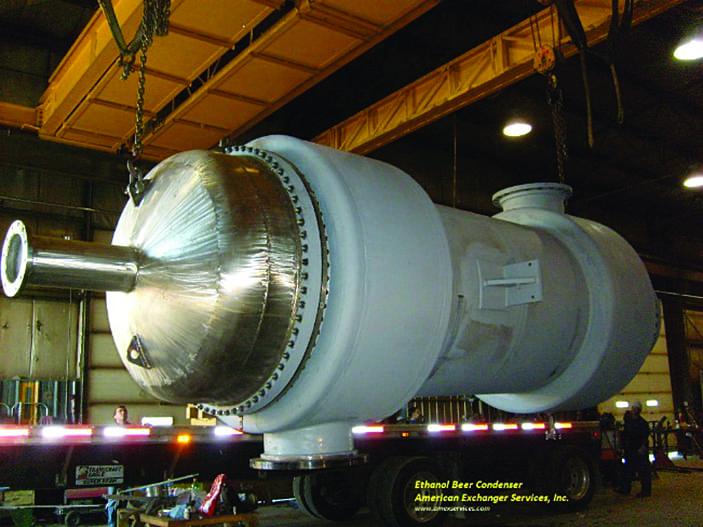
Figure 3. Finite element analysis was used for the design of the flexible shell element of this large exchanger
Flexible shell elements and FEA. TEMA focuses substantial attention on expansion joints in fixed-tubesheet heat exchangers. It provides a method for providing reproducible results independent of the program or platform used to perform the analysis. Finite element analysis (FEA) is used for the flexible shell element (FSE) design. Figure 3 shows a large exchanger designed with FEA using the FSE approach.
ASME has moved toward making the tubesheet a BPVC-designed element using its unfired heat exchanger (UHX) section. For some exchangers, the design lies outside the scope of UHX. In such situations, it is recommended to consult good design practice and perform FEA on the tubesheet.
API STANDARD 660
The API 660 Standard for shell-and-tube heat exchangers is a tight, focused standard that requires a savvy and experienced end user, working with a manufacturer who understands and has worked extensively with user and process standards to achieve a highly reliable exchanger. It will result in a more costly heat exchanger, but one that will presumably be more reliable. The additional cost, however, may be small compared to the costs of loss of availability from tube failures, cross-contamination and in situations which the fluids are a potential safety concern. This is especially true when compared to the cost of an entire project.
An extensive collection of good practices and checklists are included in the annex sections of API 660. These are very useful and provide guidance on some of the more specific issues associated with petroleum-refinery operations.

I really enjoyed this post. You describe this topic very well. I really enjoy reading your blog and I will definitely bookmark it! Keep up the interesting posts! Thanks for sharing informative blog. Visit here: “ Heat Exchanger Manufacturers”
RispondiEliminaIt was very useful information thanks for share it and you explained it well.
RispondiEliminaheat exchanger manufacturers
Questo commento è stato eliminato dall'autore.
RispondiElimina