Flow Maldistribution in Plate Heat Exchangers (Part 1)

Plate heat exchangers (PHE) are characterized by high heat transfer efficiency and compactness. An exploitation problem of PHE is related to a flow maldistribution, which can make part of the PHE idle. Usually, PHE play an important role in larger systems and their malfunction can significantly influence the whole system. Geometrical modifications of PHE can help in reducing the flow maldistribution. It is advisable to keep modifications to a minimum, so as not to hinder the production process. This can be achieved by placing additional baffles inside the PHE headers. There is a large number of possible arrangement for these baffles and to test all of them would be impractical and can take a prohibitively long amount of time for experimental measurements.
A typical PHE is characterized by a complex system of channels. Numerical calculations of its 3D model can be prohibitively time and resource consuming. The present work introduces a physically consistent methodology making it possible to reduce real 3D geometry to a 2D representation. Consequently, this permits the investigation of a wide range of parameter space and various geometrical modifications and, ultimately, optimizes the performance of the PHE. To simulate a flow inside the PHE, an incompressible flow model was used.
The plate heat exchanger (PHE) has a very efficient exchanger design but compared to other design solutions, it can demonstrate a few exploitation problems due to uneven flow distribution in its channels. The experimental and numerical studies presented in (1) confirm the existence of the maldistribution problem in practically every type of PHE design. The work (1) provides a comprehensive review of different possible causes that may lead to flow maldistribution. This can be provoked by mechanically-driven factors such as fouling, fabrication tolerances, a bypass or poor header performance, or may be related to the thermodynamic character of the ongoing processes (two-phase instabilities, heat transfer induced by changes of viscosity or density) (2).
The flow maldistribution problem is reported in nonphase change applications (3, 4) as well as in PHE condensers and evaporators (5, 6, 7, 8). The uneven load of PHE channels is especially undesirable in the case of evaporators. It can create dead zones in the furthest channels on the refrigerant side of the PHE and the vapor may be trapped in certain parts of the device, causing a local dry out or overheat.
The existing solutions for balancing the flow in PHE are mainly related to an inlet header modification. Some solutions consider adding additional inlet baffles (9), rearranging the configuration of the channels (10) or introducing internal two-phase distributors to the inside the exchanger (11).
Current studies are built on the assumption that flow maldistribution can be minimized by the geometrical optimization of the PHE. The easiest modification includes the introduction of additional obstacles or separators to the header pipe of the PHE. In practice, there is a large number of possible modifications. To examine all of them experimentally is impractical, but can potentially be achieved by the means of a fast and reliable numerical model. The main challenge in the numerical modelling of a real PHE is related to its very complicated geometry and requirement of a high resolution mesh to properly capture the dynamics of flow, heat transfer and phase change. In the research (12), computations like that were shown to require hundreds of millions of computational cells. This makes it impractical to study a wide range of parameter space and geometrical modifications.
The main objective of the present study was to create a robust methodology to transform the 3D geometry of a real PHE to its 2D representation. It was helpful to develop a fast and accurate 2D model of PHE which was used to investigate flow behavior in the PHE and to optimize its performance. In our work (12), the reduction of the 3D geometry to its 2D representation was successfully carried out and confirmed by comparison with experimental results. Nevertheless, it considered only a single pair of plates (one channel). In the current studies, a whole, multi-plate PHE is considered, and crucial additions to the 2D model were shown to be necessary in order to correctly imitate the real geometry.
The proposed methodology of a 2D reduction was based on the preservation of geometrical and flow features, and a pressure drop balance. This resulted in computational mesh that was smaller in orders of magnitude and permitted the investigation of a wide range of geometrical modifications and flow conditions. The main focus was placed on the hydrodynamics of the flow in PHE and its response to the proposed modifications. To minimize the influence of other factors, an incompressible and single-phase flow was studied.
2D NUMERICAL MODEL
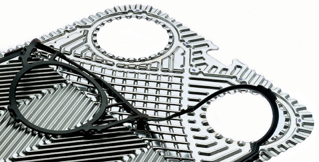
A plate heat exchanger usually consists of a large number of plates, which form flow channels when assembled together. The shape of the plate design is typically based on chevron patterns, Figure. 1. This intensifies the turbulence and heat transfer.

To reproduce the wavy (chevron) flow pattern, zerothickness mixing baffles were introduced to the inside of the 2D flow channels. They were placed alternately on both plates as shown in Figure 2. This approach was previously introduced and tested by the authors in (12). The amount of baffles was determined by the analysis of the considered real 3D PHE geometry, which was equal to 26. Another critical aspect of the 3D to 2D transformation was the preservation of a pressure loss balance.

Figure 2. Sketch of the considered 2D model of PHE. The similarity to the 3D geometry is assured by: mixing baffles in the flow channels (red) and throttling baffles to preserve a pressure balance between the 2D and 3D geometries (blue).
Throttling baffles
The analysis of the proposed 2D geometry when compared to its 3D original, shows a discrepancy in pressure balance across the PHE. Although the rectangular 2D header was modeled to preserve the inlet cross-section area, it did not conserve the same hydraulic diameter for the circular 3D header. To assure the same ratio of the pressure drop for 3D and 2D geometries, it was necessary to add an extra pressure drop Δp + :

where ∆ph 3D and ∆ph 2D are the total pressure losses in the header of 3D geometry and its 2D representation respectively, ∆pc 3D and ∆pc 2D are total losses in the channels of the 3D and 2D geometries respectively.
Differences in the hydraulic diameters of the headers result in: ∆ph 3D < ∆ph 2D. Recalling that Rec and the geometrical dimensions of the channels remain the same for both 3D and 2D geometries, the Eq. (1) can be expanded to:

For simplification, the local losses at the inlets and outlets of the channels are assumed to be the same in 3D and 2D. Finally, the value of the additional local pressure loss coefficient, which is needed to assure pressure balance in Eq. (1) is:

The additional pressure drop from Eq. (3) can be achieved by placing throttling baffles at the inlets to the 2D PHE channels, see Figure 2. The size of the individual baffle can be determined by assuming the same working principle of a sliding bolt. The value of the pressure loss coefficient in the function of an opening for this type of obstacle is presented in Table 2. This is sufficient to estimate the hydraulic diameter Db of an individual baffle

Continue
Credits:
Ziemowit Miłosz Malecha
Wroclaw University of Science and Technology | WUT · Department of Cryogenic, Aviation and Process Engineering
Ziemowit Miłosz Malecha
Paweł Płuszka
Paweł Płuszka
Arkadiusz Brenk

Commenti
Posta un commento