Basic Design Methods of Heat Exchanger

Heat exchangers (HE) are devices that transfer energy between fluids at different temperatures by heat transfer. Heat exchangers may be classified according to different criteria. The classification separates heat exchangers (HE) in recuperators and regenerators, according to construction is being used. In recuperators, heat is transferred directly (immediately) between the two fluids and by opposition, in the regenerators there is no immediate heat exchange between the fluids. Rather this is done through an intermediate step involving thermal energy storage. Recuperators can be classified according to transfer process in direct contact and indirect contact types. In indirect contact HE, there is a wall (physical separation) between the fluids. The recuperators are referred to as a direct transfer type. In contrast, the regenerators are devices in which there is intermittent heat exchange between the hot and cold fluids through thermal energy storage and release through the heat exchanger surface or matrix. Regenerators are basically classified into rotary and fixed matrix models. The regenerators are referred to as an indirect transfer type.
This chapter discusses the basic design methods for two fluid heat exchangers. We discuss the log-mean temperature difference (LMTD) method, the effectiveness method, dimensionless mean temperature difference () and (P1 – P2) to analyse recuperators. The LMTD method can be used if inlet temperatures, one of the fluid outlet temperatures, and mass flow rates are known. The ε – NTU method can be used when the outlet temperatures of the fluids are not known. Also, it is discussed effectiveness-modified number of transfer units () and reduced length and reduced period () methods for regenerators.
2. Governing equations
The energy rate balance is
For a control volume at steady state, . Changes in the kinetic and potential energies of the flowing streams from inlet to exit can be ignored. The only work of a control volume enclosing a heat exchanger is flow work, so and single-stream (only one inlet and one exit) and from the steady-state form the heat transfer rate becomes simply [1–3]
For single stream, we denote the inlet state by subscript 1 and the exit state by subscript 2.
For hot fluids,
For cold fluids,
The total heat transfer rate between the fluids can be determined from
where U is the overall heat transfer coefficient, whose unit is W/m2 oC and is log-mean temperature difference.
3. Overall heat transfer coefficient
A heat exchanger involves two flowing fluids separated by a solid wall. Heat is transferred from the hot fluid to the wall by convection, through the wall by conduction and from the wall to the cold fluid by convection.
where and and U is the overall heat transfer coefficient based on that area. Rt is the total thermal resistance and can be expressed as [1]
where Rf is fouling resistance (factor) and Rw is wall resistance and is obtained from the following equations.
4. Thermal design for recuperators
Four methods are used for the recuperator thermal performance analysis: log-mean temperature difference (LMTD), effectiveness-number of transfer units (), dimensionless mean temperature difference () and (P1 – P2) methods.
4.1. The log-mean temperature difference (LMTD) method
The use of the method is clearly facilitated by knowledge of the hot and cold fluid inlet and outlet temperatures. Such applications may be classified as heat exchanger design problems; that is, problems in which the temperatures and capacity rates are known, and it is desired to size the exchanger.
4.1.1. Parallel and counter flow heat exchanger
Two types of flow arrangement are possible in a double-pipe heat exchanger: parallel flow and counter flow. In parallel flow, both the hot and cold fluids enter the heat exchanger at the same end and move in the same direction, as shown in Figure 1. In counter flow, the hot and cold fluids enter the heat exchanger at opposite end and flow in opposite direction, as shown in Figure 2.
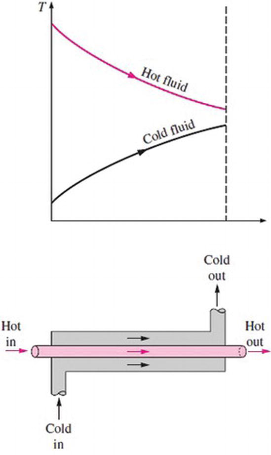
Figure 1.
Parallel flow in a double-pipe heat exchanger.
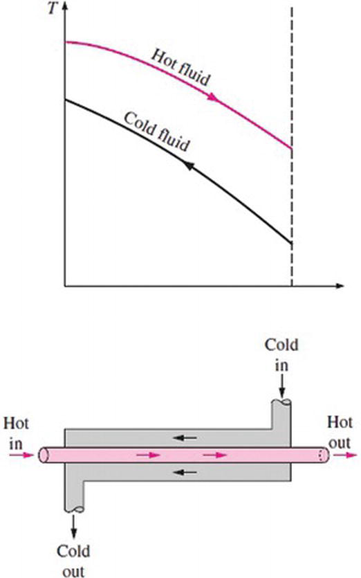
Figure 2.
Counter flow in a double-pipe heat exchanger.
The heat transfer rate is
where is log-mean temperature difference and is
Then,
where the endpoint temperatures, and , for the parallel flow exchanger are
where Thi is the hot fluid inlet temperature, Tci is the cold fluid inlet temperature, Tho is the hot fluid outlet temperature and Tco is the cold fluid outlet temperature.
The endpoint temperatures, and , for the counter flow exchanger are
4.1.3. The procedure to be followed with the LMTD method
- Select the type of heat exchanger.
- Calculate any unknown inlet or outlet temperatures and the heat transfer rate.
- Calculate the log-mean temperature difference and the correction factor, if necessary.
- Calculate the overall heat transfer coefficient.
- Calculate the heat transfer surface area.
- Calculate the length of the tube or heat exchanger
4.2. The ε – NTU method
If the exchanger type and size are known and the fluid outlet temperatures need to be determined, the application is referred to as a performance calculation problem. Such problems are best analysed by the NTU-effectiveness method [4, 5].
Capacity rate ratio is
where Cmin and Cmax are the smaller and larger of the two magnitudes of Ch and Cc, respectively, and Ch and Cc are the hot and cold fluid heat capacity rates, respectively.
Heat exchanger effectiveness εis defined as
where
or
where and are the heat capacity rates of the cold and the hot fluids, respectively, and is the rate of mass flow and cp is specific heat at constant pressure.
Heat exchanger effectiveness is therefore written as
The number of transfer unit (NTU) is defined as a ratio of the overall thermal conductance to the smaller heat capacity rate. NTU designates the non-dimensional heat transfer size or thermal size of the exchanger [4, 5].
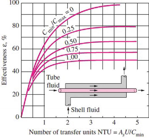
Figure 11.
Effectiveness of parallel flow.
Conclusion
This chapter has discussed the basic design methods for two fluid heat exchangers. The design techniques of recuperators and regenerators, which are two main classes, were investigated.
The solution to recuperator problem is presented in terms of log-mean temperature difference (LMTD), effectiveness-number of transfer units (), dimensionless mean temperature difference () and (P1 – P2) methods. The exchanger rating or sizing problem can be solved by any of these methods and will yield the identical solution within the numerical error of computation. If inlet temperatures, one of the fluid outlet temperatures, and mass flow rates are known, the LMTD method can be used to solve sizing problem. If they are not known, the () method can be used. () and (P1 – P2) methods are graphical methods. The (P1 – P2) method includes all major dimensionless heat exchanger parameters. Hence, the solution to the rating and sizing problem is non-iterative straightforward.
Cüneyt Ezgi (April 27th 2017). Basic Design Methods of Heat Exchanger, Heat Exchangers - Design, Experiment and Simulation, S M Sohel Murshed and Manuel Matos Lopes, IntechOpen, DOI: 10.5772/67888.


Commenti
Posta un commento