Types of Heat Exchangers

Heat exchangers are used to transfer heat energy from one fluid to another in order to control the temperature of a system or substance. Heat exchangers contain two streams of fluid, one hot and one cold, which are separated by a thermally conductive tube or plate unless the fluids are immiscible. The two streams are directed such that one transfers thermal energy to the other. Examples of heat exchanger applications include automotive radiators, boilers, furnaces, refrigerators, and air conditioning systems.
Types of Heat Exchangers
According to the heat transfer process -- the heat exchanger may use an indirect contact or direct contact heat transfer method.
- In indirect contact heat transfer, the fluids in the system are separated by a thermally conductive
 boundary layer which allows heat energy to flow but prevents mixing or contamination.
 - In direct contact heat exchangers, the fluids are immiscible (e.g. gas and liquid) and therefore do not require physical separation when transferring heat.
According to the number of fluids -- the heat exchanger may incorporate two, three, or more than three heat transfer fluids in the system.
According to flow arrangements -- the heat exchanger may be either single pass or multi-pass. It may incorporate cross-flow, counter-flow, or co-current flow. Typically heat exchangers utilize combinations of these flow patterns to maximize thermal efficiency.
- In single pass heat exchangers, fluids flow by each other only once in the system.
- Fluids in multi-pass heat exchangers are looped back to flow by each other multiple times.
- In counter flow heat exchangers, fluids flow from opposite directions towards each other.
- In cross flow heat exchangers, fluids flow perpendicular to each other.
- In co-current flow heat exchangers, fluids flow parallel to each other.
According to heat transfer mechanism - the heat exchanger uses single-phase convection, two-phase convection, and/or radiative heat transfer on each side of the exchanger.
According to construction - the heat exchanger may incorporate shell & tube, plated, or air-cooled construction. Users should keep these characteristics in mind when considering different heat exchanger  designs:
designs:- Cleanability - how easy the equipment is to clean.
- Compactness - how small or large the equipment's footprint is.
- Ease of repair - how easy the equipment is to maintain and repair.
- Extension - how easily the equipment can be modified or extended.
- Plugging risk - how susceptible the equipment is to fouling or clogging.
For the purposes of sourcing a heat exchanger, the most important classification method is construction. There are three main types of heat exchangers based on design: shell & tube, plated, and air-cooled. Within these basic types, individual heat exchangers vary greatly in design and complexity to fit the needs of specific applications and systems.
Shell & Tube
Advantages
|
Disadvantages
|
Widely known and understood
|
Less thermal efficiency than other types
|
Most versatile based on type of service
|
Subject to flow induced vibration
|
Widest range of allowable pressures and temperatures
|
Not well suited for temperature cross conditions
|
Rugged mechanical construction
|
Contains stagnant zones on the shell side which can cause corrosion
|
Subject to flow maldistribution
|
Table Credit: H&C Heat Transfer Solutions Inc.
Shell & tube heat exchangers consist of a series of round or rectangular tubes surrounded or enclosed in a larger, typically cylindrical-shaped shell or casing. The target fluid (fluid being heated or cooled) runs inside these tubes while the secondary (heat transfer) fluid flows over them inside the shell. The flow of the secondary

fluid is directed by fixed vanes in the shell known as baffles, which also provide support for the bundles of tubes.
Shell & tube heat exchangers are the most versatile type, and account for nearly 60% of all heat exchangers used. They can be used in both high and low temperature and pressure environments, and are particularly suited for high pressure applications because of their robust construction. They provide a comparatively large ratio of heat transfer area to volume and weight. They are commonly used in oil refineries, power plants, steam generators, and large chemical processes, as well as in cooling applications for hydraulic fluids and oils in engines and transmissions.
Shell Design
Shell & tube heat exchangers vary based on detailed features in construction; most notably the shell type, which determines the baffle and flow arrangement. Designs are typically based on the thermal expansion properties of the fluids and the dimensional restrictions of the overall system. Shell configurations are designated by letters; each exhibits different characteristics and has different advantages. This table provides an overview of shell types:
Shell Type
|
Description
|
Advantages
|
Disadvantages
|
E
|
-One-pass shell
-Counter- or co-current flow
|
-Many baffle types available to reduce pressure drop
-Applicable in single-phase, boiling, and condensing services
-Temperature cross possible without reverse heat transfer
|
-Reverse heat transfer possible with an even number of tube passes and no fouling
|
F
|
-Two-pass shell
-Longitudinal baffle
|
-Temperature change higher than in E-shell
-Fewer shells in series are needed
|
-Longitudinal baffle can leak if not welded
-Thermal conduction occurs across baffle
-Removable bundles are more costly to maintain
|
G
|
-Split flow
-Longitudinal baffle
-Full support plate under nozzle
|
-Split flow reduces entrance and exit velocities
-Lower risk of vibration
-Suited for horizontal shellside reboilers
|
-Fewer tube-pass options with removable bundle
-Thermal conduction occurs across baffle
-Temperature profile not as good as counter- or co-current flow
|
H
|
-Double split flow
-Two longitudinal baffles
-Full support plate under nozzles and at shell midpoint
|
-Double split flow lowers entrance and exit velocities and provides more support than G-shells
-Suitable horizontal shellside reboilers
|
-More nozzles than G-shells
-Thermal conduction occurs across baffle
-Temperature profile not as good as counter- or co-current flow
|
J
|
-Divided flow
-Full support plate under center nozzle
|
-Split flow lowers velocities
-Many baffle types are available to reduce pressure drop
|
-More nozzles than an E-shell
-Temperature profile not as good as counter- or co-current flow
|
K
|
-Kettle reboiler or vaporizer
-Liquid disengages from vapor in dome
-Nozzle for liquid draw-off is not required for vaporizers
|
-Low pressure drop
-Circulation promotes wet-wall boiling
|
-Larger shell requires entrainment calculations
-Circulation is complicated, which could lead to the buildup of heavy components
|
X
|
-Crossflow
-Multiple nozzles typical for flow distribution
|
-Low pressure drop due to single cross pass
-Temperature cross is possible without reversible heat transfer
-Applicable to single-phase, boiling, and condensing services
|
-Mal-distribution is possible, often requiring the use of a distribution plate
-Multiple nozzles are common
-Removal of noncondensables is complicated for X-shell condensers
|
Table Credit: American Institute for Chemical Engineers (AIChE) - Selecting a Heat Exchanger Shell
Some of these shell types are pictured below:
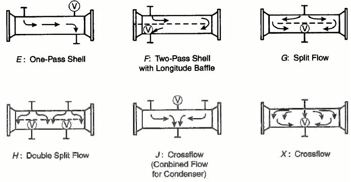
Image Credit: IUPUI.edu
Tube Design
Shell & tube heat exchangers can also vary based on the tube design and configuration.
Corrugated or enhanced surface tubes contain small ridges which increase surface area for improved heat transfer.
Finned tubes are tubes with multiple fins (thin plates) protruding from the tube wall to increase the surface area for heat transfer. Finned-tube heat exchangers are used when the heat transfer coefficient on the outside of the tubes is appreciably lower than that on the inside, typically in liquid to gas applications. They should be used when the operating pressure needs to be contained on one fluid side. They are less ideal for high velocity or boiling liquid applications where convective heat transfer plays a large role, and can actually impede heat transfer in these situations.
Straight tubes are configured with no bends or curves. They are able to handle heavy fouling fluids or applications where temperature cross conditions exist (when the fluid being heated has an outlet temperature that falls between the inlet and outlet temperature of the heating medium).
U-tube heat exchangers consist of bundles of straight tube bent in a U shape. These designs require less tubing than straight configurations, so manufacturing costs are lower. They utilize a floating design so thermal stress is also not an issue. However, because of the bend, maintaining (cleaning the insides) and replacing U-tubes can be difficult or costly. These designs utilize true counter-current flow; this eliminates the correction factors needed in traditional shell & tube exchangers due to the use of both counter-current and co-current flow.
- Hairpin heat exchangers are U-tube heat exchangers with separate cells for both inner tube bundles, increasing heat transfer efficiency. They are the best choice for applications that call for a temperature cross.
Tube sheets or bundles can also either be fixed or floating.
- Floating or floating-head heat exchangers have one tube sheet connected to the shell and another that is free floating. This eliminates thermal stress between the tube bundle and shell, often at the cost of heat transfer efficiency and simplicity.
- Fixed heat exchangers have all tube sheets or bundles attached and fixed to the shell. They are less complex and cheaper to manufacture and maintain than floating tube-sheet configurations, but can suffer from thermal stresses due to restraints between the shell and tubes.
Plated
Advantages
|
Disadvantages
|
Low initial purchase cost
|
Narrower range of allowable pressures and temperatures
|
Many configurations available
|
Narrow flow paths are subject to plugging/fouling
|
Higher heat transfer efficiency
|
Gasketed units require specialized opening and closing procedures
|
Lower fouling due to high turbulence in the exchanger
|
Material selection is critical due to thin wall thicknesses
|
Can achieve significant temperature crosses
| |
Smaller footprint
|
Table Credit: H&C Heat Transfer Solutions Inc. | Image Credit: Armstrong International, Inc.
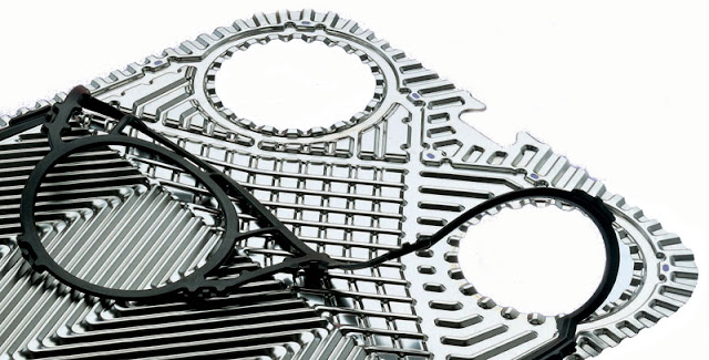
Plated or plate-type heat exchangers use metal plates instead of tubes as the thermally conductive boundary between fluids. The hot and cold fluids alternate between each of the plates, and baffles direct the fluid flow  between them. Plates are more efficient than comparatively sized tubes because of their corrugation and large surface areas. Unfortunately, it is difficult to make reliable seals for large gaskets between these plates, often limiting these heat exchangers to smaller-scale applications. They are often used in low-viscous applications with low to moderate demands on operating temperatures and pressures, typically below 150°C. Recently, new improvements in gasket design and heat exchanger design have allowed plate type heat exchangers to be used more regularly in large scale applications.
between them. Plates are more efficient than comparatively sized tubes because of their corrugation and large surface areas. Unfortunately, it is difficult to make reliable seals for large gaskets between these plates, often limiting these heat exchangers to smaller-scale applications. They are often used in low-viscous applications with low to moderate demands on operating temperatures and pressures, typically below 150°C. Recently, new improvements in gasket design and heat exchanger design have allowed plate type heat exchangers to be used more regularly in large scale applications.
There are three main types of plated heat exchangers: plate and frame heat exchangers, spiral plate heat exchangers, and plate coil heat exchangers.
Plate and Frame
Plate and frame heat exchangers consist of a number of corrugated metal plates in mutual contact. There are four main types of plated heat exchangers based on the way the plates are held together.
Brazed plate heat exchangers consist of specially formed plates, vacuum brazed together to form a heat transfer device. They are used in many industrial and refrigeration applications. These heat exchangers are typically composed of stainless steel plate with copper brazing, making them extremely corrosion resistant. They are also very economical due to their compactness and high efficiencies.
Gasketed plate heat exchanged use high quality gaskets to seal and clamp together plates and protect against leaks. The gasketed plates are assembled in a pack, mounted on upper and lower guide rails, and compressed between two end frames by compression bolts. The gasket arrangement of each plate distributes the hot and cold media in a counter-flow arrangement into alternating flow channels through the plate pack. These heat exchangers are simple and cheap to maintain, since the plates can be easily removed.
Welded plate heat exchangers require no gaskets; instead the plates are welded together. These heat exchangers are typically constructed of a singe material (most commonly stainless steel). They are extremely durable and are ideal for high temperature applications and highly corrosive fluids. However, since the plates are welded together they cannot be cleaned mechanically like gasketed heat exchanger plates.
Semi-welded heat exchangers are a mixture of welded and gasketed plates. They consist of pairs of plates welded together and gasketed to other pairs. In this setup, one fluid path is welded and the other is gasketed. This allows one fluid path (the gasketed side) to be easily cleaned and serviced, while the other (the welded side) can handle more intense fluids. Semi-welded heat exchangers are often used for handling expensive materials since fluid loss is very unlikely.
Spiral Plate
Spiral plate heat exchangers (SPHEs) are a type of welded plate heat exchanger with two parallel curved (spiral shaped) metal plates. These plates create extremely high turbulent flow in a counter-current pattern. These heat exchangers are very versatile, and can be used with high-viscosity fluids and fluids with high and heavy suspended solids content without clogging or requiring frequent cleaning.
Plate Coil
Plate coil or panel coil heat exchangers are a hybrid of tube heat exchangers and plate heat exchangers. They consist of coils of tube containing a heat transfer fluid connected or adjacent to a plate, panel, or wall which holds another fluid. These devices are relatively inexpensive and simple to maintain since the coils can be easily removed. They can be made into a variety of shapes for different applications, including the heating or cooling of fluids in tanks.
Air Cooled
Advantages
|
Disadvantages
|
Useful for locations where cooling water is scarce or expensive to treat
|
High initial purchase cost
|
Well suited for high temperature process streams
|
Relatively large footprint
|
Low maintenance and operating costs
|
Higher process outlet temperature
|
Table Credit: H&C Heat Transfer Solutions Inc.
Air cooled heat exchangers (ACHEs), also called "fin-fans", are designed to use air to directly reject heat from a n immiscible fluid stream. They typically consist of fans which push air over the surface of tube bundles or plates which contain the process fluid to be cooled. They provide an alternative to standard water-cooled shell & tube heat exchangers, particularly when water is in short supply. These heat exchangers can be used in a wide range of applications and climates. They are simpler and less costly to operate and maintain than water coolers, since air poses no risk of corrosion or process fluid contamination. Air coolers also have fewer problems associated with environmental concerns and government regulations.
n immiscible fluid stream. They typically consist of fans which push air over the surface of tube bundles or plates which contain the process fluid to be cooled. They provide an alternative to standard water-cooled shell & tube heat exchangers, particularly when water is in short supply. These heat exchangers can be used in a wide range of applications and climates. They are simpler and less costly to operate and maintain than water coolers, since air poses no risk of corrosion or process fluid contamination. Air coolers also have fewer problems associated with environmental concerns and government regulations.
Air cooled heat exchangers may be either forced draft or induced draft.
Forced Draft
Forced draft heat exchangers "force" or push air through the unit by installing fans at the inlet below the tube bundle. These types of ACHEs have lower power consumption for a given air mass flow rate than induced draft configurations. The position of the fans and fan drives makes them easier to maintain and eliminates their exposure to high temperatures. However, forced draft heat exchangers are susceptible to hot air recirculation due to low air exit velocities, often resulting in lower cooling efficiencies. Airflow distribution is also more variable in forced draft designs, and performance is subject to changes based on weather effects.
Induced Draft
Induced draft heat exchangers pull air through the unit by installing fans at the outlet above the tube bundle. These types of ACHEs provide more even airflow distribution for more reliable and predictable heat transfer, which is essential for critical cooling applications. They also are less prone to hot air recirculation which decreases the overall cooling capacity. However, they tend to consume more power and are more difficult to maintain due to the accessibility of the fans. They also tend to take up more space and are more prone to vibration.
Specifications
A typical heat exchanger selection form or selection request requires the user to submit a number of different specifications to the manufacturer in order to design the product. When sourcing a standard heat exchanger, these same specifications should be understood in order to properly select the right design for the application.
Heat transfer rate, also known as the capacity or heat load, is a measure of the heat energy transferred in the heat exchanger per unit time. This is the most fundamental specification for describing heat exchanger performance, and must be known by the user before selecting a heat exchanger or sending a selection form to a manufacturer. The general heat transfer equation can be used to calculate the heat load given the fluid temperature change (of either fluid channel), the fluid flow rate, and the specific heat:
Q=[mdot x cp x ΔT]cold = -[mdot x cp x ΔT]hot
Where:
mdot = mass flow rate
cp = specific heat of the fluid
ΔT = difference in temperature between the fluid in and fluid out
The mass flow rate (mdot) can be calculated for water or air using these equations:

Equations Credit: Lytron, Inc.
Oversurfacing is a factor of safety approach often used in heat exchanger design as a means of arbitrarily increasing the heat-transfer surface area to allow for fouling. Fouling is any type of material deposit on the heat exchanger surface that adds heat transfer resistance and reduces efficiency. Oversurface is the percentage the surface area is increased above the requirements for the heat exchanger at clean conditions. This value can range from 15 to 50% depending on the application's susceptibility to fouling and other application factors.
The hot side medium or fluid is the fluid that enters the heat exchanger at a higher temperature. In cooling applications, the hot medium is the target fluid being cooled (e.g. steam); in heating applications, the hot fluid is the heat transfer medium (e.g. water).
The cold side medium or fluid is the fluid that enters the heat exchanger at a lower temperature. In cooling applications, the cold medium is the heat transfer medium (e.g. coolant); in heating applications, the cold fluid is the target fluid being heated.
Selection Tip: Specific heat, viscosity, density, latent heat, thermal conductivity, and operating pressure are all important properties to consider when selecting heat exchanger fluids. For more information, visit heat transfer fluids and thermal oils.
The rest of the specifications listed below are typically designated twice, once for each side (hot side and cold side) of the exchanger:
Flow rate is a measure of the rate at which the heat transfer fluids flow through the heat exchanger, commonly measured in gallons per minute (gpm) for liquids and cubic feet per minute (cfm) for gases. Heat transfer efficiency increases with increasing flow rate in a heat exchanger, but flow is limited by the size of the pump available and the maximum allowable pressure drop in the system (which also increases with flow rate).
Allowable pressure drop designates the highest pressure drop acceptable for the system. The pressure drop is a limiting factor on the size, flow rate, and efficiency of heat exchanger design. As pressure drop increases, more powerful and energy intensive pumps are needed, so this specification should be matched according to the desired pumping requirements for the system.
Maximum allowable working pressure (MAWP) or design pressure is the maximum pressure the heat exchanger and its components are designed to withstand. On a heat exchanger design/selection sheet, the design pressure indicates the highest pressure the system will reach during normal operation. It is typically the maximum normal operating pressure plus a design margin. This specification is particularly important for designing the thickness of the pressure retaining components in the heat exchanger system.
Maximum/minimum temperature or design temperature is the highest or lowest temperature or range of temperatures the heat exchanger will handle during normal operation. Often manufacturers will request both inlet and outlet temperatures for each side of the heat exchanger. Design temperature is defined by the process conditions of the application. It is typically the maximum normal operating temperature plus a design margin. Manufacturers build heat exchangers based on these temperatures.
Materials of Construction
Heat exchanger materials (particularly those for the tubes or sheets in contact with the fluid) are a very important part of heat exchanger design and selection. Optimum material properties include high thermal conductivity for efficient heat transfer, high strength to withstand high operating pressures, high corrosion resistance to withstand corrosive fluids over time, and low cost. Common materials for heat exchangers include copper, brass, aluminum, and stainless steel.
Copper has the best heat transfer performance of all metals commonly used in heat exchangers, due to its high thermal conductivity. However, by itself copper has relatively poor corrosion resistance to more aggressive fluids. It is commonly used with water and many standard coolants.
Brass, an alloy of copper and zinc, is stronger than copper while still retaining high thermal conductivity for efficient heat transfer. Brass still suffers from corrosion resistance, though not as much as pure copper. Brass alloys with higher amounts of zinc are more resilient, but at the cost of heat transfer performance.
Aluminum is a lightweight metal commonly used for heat transfer tubes because it has high heat transfer efficiency at a comparatvely low cost. Aluminum used in heat exchangers is commonly alloyed with bronze and nickel to increase its corrosion resistance. It is excellent for use with ethylene glycol/water solutions (EGW) and oils.
Stainless steel is an alloy of steel with excellent corrosion resistance. Compared to other heat exchanger metals, stainless steel has a lower heat transfer efficiency and is often more expensive. It is best suited for working with corrosive and aggressive heat transfer fluids such as deionized water.
Other material choices when dealing with highly corrosive fluids include nickel alloys and titanium alloys.
Connections
Finally, it is essential that heat exchanger can be properly connected to the system it is being integrated into. Standard connection types include:
- Flanges -- protruding rims or collars that are bolted flush together to connect tubes or pipes.
- Pipe threading -- screw threaded ends sized based on national pipe thread (NPT), British standard pipe thread (BSPT), metric, or other standards.
- Soldering -- connecting pipe or tube ends using a filler metal (solder).
For more information on connection types, visit Pipe Fittings or Tube Fittings on GlobalSpec.
References
Image Credits

Commenti
Posta un commento