Pressure Drop effects on design of Plate Heat Exchangers
 After calculating the exit temperatures in the rating calculation, or having determined the flow length in the sizing calculation, the pressure losses may be calculated. The pressure loss for each stream through the heat exchanger finned passages is calculated by
where subscripts 1 and 2 denote the entering and leaving fluid density.
The terms of Equation 1 are entrance loss, flow acceleration loss, core friction, and exit loss, respectively. The Kc and Ke values depend on the cross-sectional flow geometry, σ and Re. Figure 1 gives Kc and Ke for a 1:1 ratio channel (Kays and London, 1984). Kays and London (1984) give similar curves for two other channel geometries (parallel-plate channel and triangular channel). The entrance and exit losses are normally < 10% of the total core loss, so the data of Figure 1 will cover most situations with adequate accuracy. The differences due to other channel configurations should cause only a second-order effect for most situations. Figure 1 is based on a uniform velocity entering the heat exchanger and fully developed flow in the core, and at the exit. This assumption is not valid for interrupted fin surfaces. In this case, Kays and London (1984) recommend the use of the Re = ∞ curves to evaluate Kc and Ke. In this case, all channel configurations have the same Kc and Ke values for Re = ∞. The calculation steps for the core pressure loss requires the information developed through step 6 of the rating calculation procedure. After calculation of the Kc and Ke values and the densities entering and leaving the core (ρ1, ρ2), the core Δp may be calculated using Equation 1.
Figure 1 Entrance and exit loss coefficients for multiple square channels with abrupt contraction entrance and abrupt expansion exit. Reynolds number is marked as NR = Re, from Kays and London (1984)

The wavy and herringbone fin geometries are generically similar. Both have a “wavy” flow path, however, the herringbone wave form is that of a chevron and the wavy is in the form of a smooth wave. Dong et al. (2007) provide an empirical power law correlation for herringbone fins. Their correlation is based on data for 11 herringbone fin geometries. The j and f versus ReDh correlations are given by
Although the performance of the many different corrugation forms can vary considerably, the isothermal channel pressure loss in a plate heat exchanger can always be calculated from a friction factor type of equation:
Here L is the flow length given by the ratio of plate area and channel flow width.
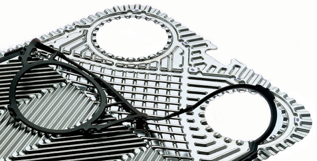
A plate heat exchanger (PHE) comprises a pack of spaced corrugated plates arranged such that the two heat exchanging fluids flow through alternate spaces in the pack. The corrugations maintain the gap between adjacent plates which are sealed against each other. These are nowadays several different technologies to effect a seal between the plates and to maintain the pack in a compressed state.
Normally plates are pressed and expensive tools are required for their production. Unlike shell-and-tube units, plates are produced in a limited number of sizes and are never custom made to individual requirements. However, the flexibility of their arrangement enables a particular duty to be easily handled by the correct selection of standard components.
The big differences between the
predicted and the measured pressure drops
indicate that it is necessary to test all new
patterns instead of relying on simulated
predictions only
Pattern A plate is an asymmetric plate
designed to have a low pressure drop. It is
mainly used for liquid and steam
processes.

The investigated angles of flow direction
for pattern A. Normal flow direction being an angle
of 0°
This pattern was tested for different
directions of the flow since these can cause
misdistribution of the medium throughout
the channel. Due to lack of the sample
plates only the steam side was tested.
The two graphs (fig. 5 and 6) show
that the predictions of the pressure drop
made were too low and that the pressure
drop increases with the angle of the
direction of the flow

Figure 5: Fanning s friction factor for different
inflow angles of water on the steam side of a
pattern A channel
Pattern A, Steam side: 0 degrees

Figure 6: A comparison of the predicted and
measured values for the direction of the current
flow
The pattern B plates can be arranged to
make three different channels: narrow
(NH), wide (SH) and medium (SS). The
pressure drops in these were compared to
the predicted ones. The results include the
comparison for the heat transfer areas as
well as for the whole channels

Figure 7: The predicted and the measured values for
the pattern B SH channel

Figure 8: The predicted and the measured values for
the pattern B NH channel
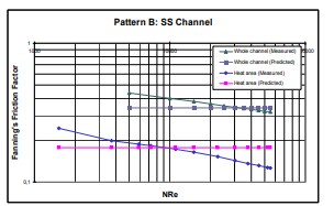
Figure 9: The predicted and the measured values for
the pattern B SS channel
The graphs show the same difference in
tendencies for the heat transfer areas as for
the whole channels. The second thing to be
noted is that although they all come from
the same plate the different channels show
different pressure drop tendencies.
The pressure drop over several
channels instead of just one should also be
examined. The pressure drop for several
channels is not necessary just a multiple of
one channel.
Typical velocities in plate heat exchangers for waterlike fluids in turbulent flow are 0.3-0.9 m/s but true velocities in certain regions will be higher by a factor of up to 4 due to the effect of the geometry of the plate design. All heat transfer and pressure drop relationships are based on either a velocity calculated from the average plate gap or on the flow rate per passage.
Figure 2 illustrates the effect of velocity on pressure drop and film coefficient. The film coefficients are very high and can be obtained for a moderate pressure drop.
One particularly important feature of the plate heat exchanger is that the turbulence induced by the troughs reduces the Reynolds number at which the flow becomes laminar. Typical values at which the flow becomes laminar varies from about 100 to 400, according to the type of plate. The friction factor is correlated with:

where y varies from 0.1 to 0.4 according to the plate and B is a constant for the plate.

One other field suitable for the plate heat exchanger is that of laminar flow heat transfer. It has been previously pointed out that the exchanger can save surface by handling fairly viscous fluids in turbulent flow because the critical Reynolds number is low. Once the viscosity exceeds 20-50 cP, however, most plate heat exchanger designs fall into the viscous flow range. Considering only Newtonian fluids since most chemical duties fall into this category, laminar flow can be said to be one of three types:
- Fully developed velocity and temperature profiles (i.e., the limiting Nusselt case);
- Fully developed velocity profile with developing temperature profile (i.e., the thermal entrance region); or
- The simultaneous development of velocity and temperature profiles.
The first type is of interest only when considering fluids of low Prandtl number, and this does not usually exist with normal plate heat exchanger applications. The third is relevant only for fluids such as gases, which have a Prandtl number of about one.
For type 2 correlations for heat transfer and pressure drop in laminar flow are in the form
(2)

where
- Nu = Nusselt number (αd/λ.),
- Re = Reynolds number (Vdρ/η),
- Pr = Prandtl number (cpη/λ) ,
- η/ηp = Sieder Tate correction factor
and
(3)

where f is the friction factor and a is a characteristic of the plate.
From this correlation it is possible to calculate the film heat transfer coefficient, for laminar flow. This coefficient, combined with that of the metal and the calculated coefficient for the service fluid together with the fouling resistance, are then used to produce the overall coefficient. As with turbulent flow, an allowance has to be made to the Log Mean Temperature Difference to allow for either end-effect correction for small plate packs and/or concurrency caused by having concurrent flow in some passes. This is particularly important for laminar flow since these exchangers usually have more than one pass.
Owing to particular geometry of plate corrugation Reynolds value in a PHE from laminar to turbolent regime is 200, while in a Shell & Tube typical value is 1,500.
Plate Heat Exchangers design software is evaluating heat transfer area for a required duty with relevant LMTD assuming a proper K value and later on is going to verify if calculated plates/channels are able to match max pressure dop. In negative case software is adding plates/channels to reach amount of channels able to get pressure drop design/calculated.
Estimation of pressure drop through simulation is not always accurate (especially in case of high viscosity fluids or non newtonian fluids) there as thumb rule is better to keep some margin when pumps should be selected in order to have enough prevalence of the pump in the circuit.


#Thanks for this kind of information it is very useful. Keep it up.
RispondiEliminahttps://windowsroom.com/pipe-flow-expert/
This site have particular software articles which emits an impression of being a significant and significant for you individual, able software installation.This is the spot you can get helps for any software installation, usage and cracked.
RispondiEliminaprocrackeys.com
geometric-glovius-pro-crack
pipe-flow-expert-crack
autoplay-media-studio-crack
virtual-audio-cable-crack
ivt-bluesoleil-crack
So nice I am enjoying for that post as for u latest version of this Security tool Available
RispondiEliminapipe flow expert crack
Thanks for sharing such a great post. Nice Post I Enjoyed!
RispondiEliminaGillmeister Rename Expert Crack
Sublime Text Crack
I guess I am the only one who came here to share my very own experience. Guess what!? I am using my laptop for almost the past 2 years, but I had no idea of solving some basic issues. I do not know how to saqibtech.net But thankfully, saqibtech.net
RispondiEliminadrylab system crack
file manager local and cloud file explorer crack
microsoft activation scripts with crack
tuneskit drm m4v converter crack
automatic call recorder pro crack
Questo commento è stato eliminato dall'autore.
RispondiEliminaThanks for all the formulas, I really like the methods and techniques you have used in the equations!
RispondiEliminaCable sizing calculator australia
This blog does a great job explaining the plate fin heat exchanger design. It’s simple and clear, making it really helpful for anyone wanting to learn about compact heat exchangers.
RispondiElimina